We are one of the best best Demister Pad Manufacturer in Mumbai. In every process involving contact between liquid and flowing gas carry over of liquid particulate matter by gas or vapour is generally termed as "Entrainment". MIST ELIMINATOR is an entrainment eliminator manufactured exclusively by SUMIT INDUSTRIES. Sumit Industries- leading Demister pad manufacturer in Mumbai provides specially designed and fabricated bed of finely knitted wire of metallic or synthetic materials, to suit specific process configuration in existing or new equipment and provide highest performance and economy of mist eliminator available. Performance and economy result for superior engineering manufacturing and technical support.

Mist is a generic term for entrainment, where the size of entrained liquid droplets is less than 10 microns. When mist laden vapour passes through the knitted wire - mesh the vapour moves freely through the mesh but the liquid droplets, having inertia cannot follow the stream, contact the wire surfaces and are briefly held there, they coalescer merge into large droplets and eventually fall of due to gravity.
General ConfigurationAs we are best Demister pad manufacturer in Mumbai, our mesh demisters consist of a pad of knitted metal or plastic wire mesh usually sandwiched between grids for mechanical support. Except for units less than about 600mm diameter, they are normally split into sections of between 300 to 400mm wide to facilitate installation through a normal vessel man way. As per client requirement the pads are cut slightly oversize to ensure a snug fit and thus eliminate any possible vapour by - pass either between sections or between pad and vessel wall (or shroud). Each mesh pad is formed from crimped layers of fabric knitted from monofilament with the direction of the crimp rotated 90 degrees in each adjacent layer to provide a uniform voidage together with a high ratio of filament surface per unit volume of pad.
Standard support grids consist of a framework of 25mm x 3mm thick flat bar fixed to a grid consisting of 6mm rods usually spaced on 150mm centres to retain the mesh with minimum obstruction of the face of the pad. The top and bottom grids are connected by spacer rods or tie wire passing through the mesh that are welded to each grid to ensure the dimensional stability of the pad. Mesh pads can also be furnished with special heavy duty support grids where these are required to provide a working platform inside the vessel.
SUMIT mesh pads can be installed either horizontally for vertical vapour flow or vertically for horizontal vapour flow. For vertical vapour flow, mesh pads are normally either 100mm or 150mm thick and for horizontal flow are normally greater at 150 to 200mm (+) thick. Where mesh pad thickness exceeds 300mm, the unit is usually divided into 2 separate layers so that the sections will pass through normal vessel manways and in such cases wire screens are fitted between layers to maintain pad integrity during installation.
 Construction of Mist Eliminator
SUMIT mist eliminator consist of the components; the knitted wire matrix, referred to as 'mesh' and the framework, referred to as 'grids'. Grids may be constructed from material different from the mesh. Material of construction are a key consideration for maximizing the service life of the mist eliminator. Sumit mist eliminators are customs manufacturing using material specified by the client. Typical stainless steel, polypropylene and PVDF items are maintained in inventory. Other alloy steels are available by special order; other polymeric material are also available. Extremely high surface area units using co. knits of metal wire with either fibre or multifilament PTFE fibre (and others) are available by special order.
Process DesignVariables that affect the design of demister include vapour velocity, liquid entrainment loading, particle size distribution, gas and liquid viscosity and surface tension, operating temperature and pressure and materials of construction. For purpose of preliminary selection, empirical equations are presented here for the estimation of design gas velocity, pressure drop and separation efficiency.
Design VelocityThe maximum allowable vapour velocity 'V', for most systems is calculated according to the equation given below It is suggested that the design velocity should be 60-75% of 'V' to allow for surges and upset conditions However excellent performance is obtained in most systems for velocities 30-110% of the maximum allowable vapour velocity for high pressure and vacuum services the constant "K" needs a specific design.
 Pressure Drop
For process equipment at normal velocity P is usually negligible (almost < 25 mm of WG) in vacuum service high performance is routinely achieved with pressure drops 5mm WG.
Separation EfficiencyNormally Sumit mist eliminator will remove droplets down to 5 microns with an efficiency up to 99%. This efficiency will vary depending upon the particle size distribution and other operating conditions, furnished in a wide variety of mesh styles. The Sumit offer collection efficiency and pressure drop combination that can be suited exactly to specific process requirements. Special design are now available with higher efficiencies for specific applications.
Typical Arrangement Installation

All demisters (except the spiral wound type) are sectional for ease of installations through a manhole. Sections are normally 300 mm - 600 mm wide 105-152 mm thick. The Sections are not normally made longer than1900 mm due to difficulty in handling breaks in length should coincide with support beams across the vessel. Also intermediate support beams are also recommended for all spans longer than 1800-2000 mm. Pad is supported with 50 to 75 mm wide annual support ring drilled with 3 to 6 mm diameter holes and welded to the vessel wall. However, as we are topmost Demister pad manufacturer in Mumbai, all demisters are supported as per client requirement hold down bars support and annular rings diagram are supplied by the vessel fabricator.
Technical Data - Demister| SUMIT TYPE | Free Volume % | Bulk Density | Surface Area / Volume | Application / Characteristic | ||
| LB/FT3 | (kg/m3) | FT3/FT3 | M2/M3 | |||
| P.P. | 93 | 4.6 | 75 | 248 | 815 | Acid Mist / Salty Condition |
| SM | 99 | 5 | 80 | 48 | 157 | Dirty Services, Min. Pressure Drop |
| SD | 97 | 4 | 64 | 135 | 440 | Dense, Multi Wire |
| SF | 94 | 8 | 128 | 250 | 820 | Highly Corrosive Condition |
| ST | 95 | 5.5 | 85 | 220 | 725 | Highly Corrosive Condition |
| S.C. | 98.4 | 8 | 128 | 243 | 800 | Highly Corrosive Condition |
| SM | 98.2 | 9 | 144 | 86 | 282 | Standard General Purpose |
| SM | 94 | 10 | 160 | 90 | 294 | General Purpose |
| SM | 97.7 | 10.75 | 173 | 109 | 360 | General Purpose |
| SM | 97.6 | 12 | 193 | 115 | 377 | Heavy Duty, Very High Efficiency, Very Clean Services |
| SDW | 96 | 13.7 | 222 | 275 | 905 | Fine Mist Condition, Super Dense |
| SDW | 94 | 19 | 305 | 340 | 1115 | ----”---- |
| SMW | 95 | 13.5 | 215 | 250 | 820 | ----”---- |
| KM | 94.6 | 27 | 432 | 597 | 1960 | Multi Mesh Wires, Super Dense |
| SMPP | 99 | 4.5 | 70 | 62 | 204 | Low Temp Condition |
| SIPP | 99 | 4.4 | 70 | 65 | 214 | Corrosive, Low Temp Condition |
| SSPP | 99 | 5 | 80 | 77 | 254 | Low Density, General Purpose |
Sr. No. |
Material |
Liquid Product Seperated |
| 1 | S.S. 304, S.S. 304 L | General Purpose, Petroleum Fractions |
| 2 | S.S. 316, S.S. 316 L | Distillation of Alcohol, General Purpose |
| 3 | COPPER | Alcohol, Aldehyde, Amines |
| 4 | MONEL | Dilute Acid, Caustic Soda |
| 5 | NICKEL | Caustic Soda |
| 6 | ALLOY 20 | Nitric Acid, Alkaline PH |
| 7 | INCONEL 825 | Dilute Acidic Media |
| 8 | INCONEL 625 | Phosphoric Acid, Fetty Acid |
| 9 | POLYPROPYLENE | Hydrolic Acid, Corrosive Media |
| 10 | P.V.D.F. | Corrosive Services For Temperature 140oc |
| 11 | P.T.F.E. / FEP / PFA / ETFE / ECTFE | For Highly Corrosive And High Temp |
| 12 | HOSTAFLON | Sulphuric Acid Plant, Temp up to 150oc |
| 13 | GLASS WOOL | For Very fine mists |
Several factors must be considered when deciding on the configuration of vessel internals. The first step is to determine the cross-sectional area needed. Then alternative geometry and shape appropriate for both the vessel and plant location is selected. Image show ( image 1) the most typical, but by no means complete, configurations. Mist eliminators can be of virtually any size or shape to accommodate all factors.
SIMPLIFIED VIEWS OF TYPICAL MIST ELIMINATOR CONFIGURATIONS IN SEPARATOR VESSELS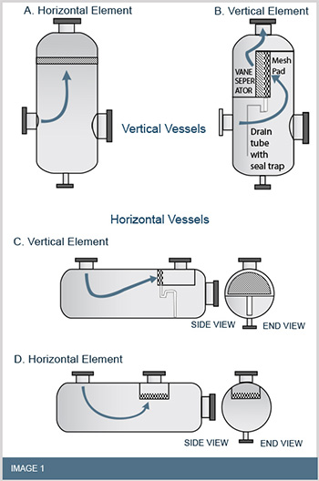

The performance of the mist eliminator depends strongly on an even velocity distribution over the cross-sectional area. Representations for specific cases are illustrated in Image show (Image 2) T small velocity differences are acceptable, but should be minimized at the design stage. Otherwise, some regions of the mist eliminator may be subjected to heavy loading leading to re-entrainment while other regions are unused.
Most often, the mist eliminator is located just upstream of the outlet nozzle with insufficient disengagement space. Vapour tends to channel through the pad in the region closest to the outlet nozzle and peripheral regions of the pad remain unused. To rectify this, Sumit engineers apply an Integral Flow Distributor which is welded to region(s) of the downstream face of the pad. This technique allows the engineer to selectively increase the pressure drop through regions of the pad likely to suffer from channelling, and is cost effective.